
Designing an autopilot control circuit
- nbocmembership
- Feb 7
- 3 min read
Autopilots on boats with hydraulic steering use an electric pump driven by a central control unit to move hydraulic fluid through existing steering lines, bypassing the helm to turn the rudder. A sensor (heading/gyro) tracks the boat's direction, allowing the control unit to make precise, constant steering corrections.
Flow and direction of hydraulic oil is controlled by valves operated by solenoids. These take very little electrical switching current since they merely open/close ports within the valve block. The force necessary to turn the rudder is generated by the electric pump.
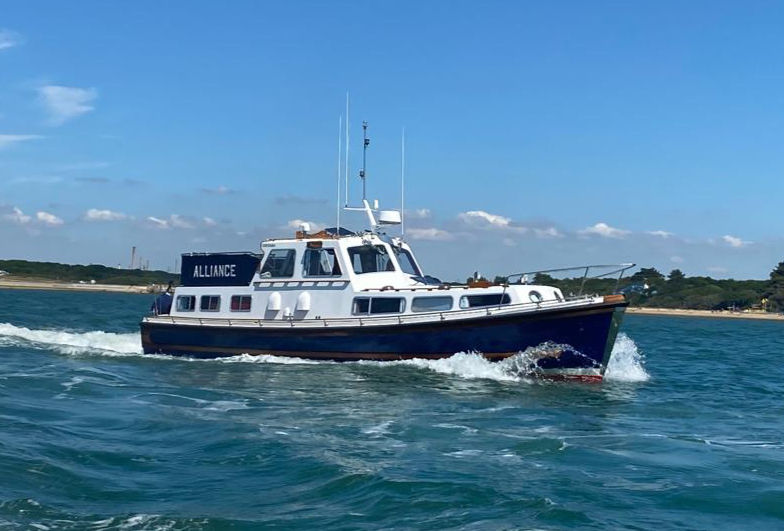
However, there are still a number of classic boats like Nelsons with mechanical steering systems such as Mathway. A mechanical linkage (often using shafts and bevel gearboxes) provides a direct, robust connection between the wheel and the rudder. The challenge is to find a way for an autopilot to control it.

Older Nelsons with mechanical steering often have a reversible electric motor with a sprocket and chain driving the steering shaft. The modern equivalent is a toothed belt of the type used in automotive engines, they're low maintenance, very reliable and don't corrode!
The next part of the challenge is how to activate a heavy duty electric motor using a modern electronic autopilot control unit. These units generally have low current switching circuits adequate for solenoids but not able to cope with higher loads.
So, you can't simply connect the autopilot to the drive motor. You need to have an extra ingredient, an electrical interface to transform low current outputs from the Autopilot into high current outputs to the motor. Sounds like a simple task, just use a few mechanical relays to do the job, right?
Wrong, because you've failed to consider what happens when the autopilot tries to change course while the motor is still spinning in the opposite direction. The electrical surges this generates will spark and burn out your relay contacts. One possible solution is to use solid state relays BUT this is not as simple as it sounds.
Relays, both mechanical and solid state, do not switch instantaneously. There is a delay to their operation which has to be considered.
Activation times in milliseconds (On / Off):
solid state relay 0.1ms / 20ms
mechanical relay 15ms / 15ms
Here is a schematic of the circuit I designed together with an explanation of its functionality.
It is drawn in the rest state, both ends of the motor connected to negative (black)
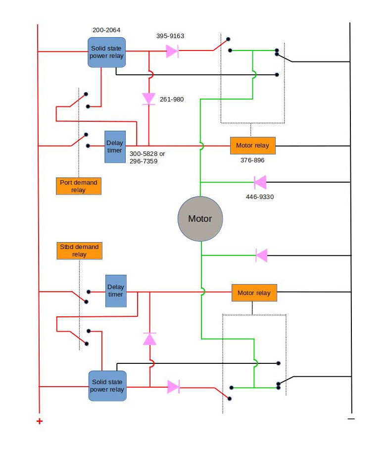
Explanation of how the circuit works
Power to the bidirectional motor is switched by a combination of solid state and mechanical relays. The relays are sequenced such that the motor relays only operate when no current is present. Delay timers ensure the motor is stationery before the Autopilot reverses direction.
Operating sequence:
ON: demand relay on, motor relay on, solid state relay on
OFF: demand relay off, solid state relay off, motor relay off
I hope some of you Nelson aficionados find this information interesting, perhaps even useful. I went through several iterations of the above design (and burned out a multitude of relays) before discovering a circuit which has worked effectively and reliably for over 20 years.
Nelsons are not renowned for steering particularly well in certain conditions, such as heavy following seas. An autopilot can only predict boat movements, it can't see the shape and direction of oncoming waves. The best algorithms have inherent compromises in them.
Sometimes the best way to maintain a comfortable course is to stand a human at the helm!


Comments